Accessing the ONT
This guide uses 192.168.11.1/24 (ONT) and 192.168.11.2/24 (WAN) for demonstration purposes. Be sure to replace the IP addresses and subnet mask with your actual default settings.
Accessing an ISP ONT
You may need to physically disconnect the fiber cable to access the management interface. The OLT can remotely disable the Local Craft Terminal (LCT) via the ONT's Administrative State (Managed Entity 256 - ITU-T G.988). Disconnecting the fiber ensures the management interface remains accessible.
WAN vs LAN
The ONT resides on the WAN side of your network, not the LAN. These are distinct networks. In their final, functional state, these two IP address spaces must be separate and unique for the router to distinguish between them. Additionally, do not conflict the ONT LCT IP with your Internet IP. Your WAN interface must be configured to accommodate both.
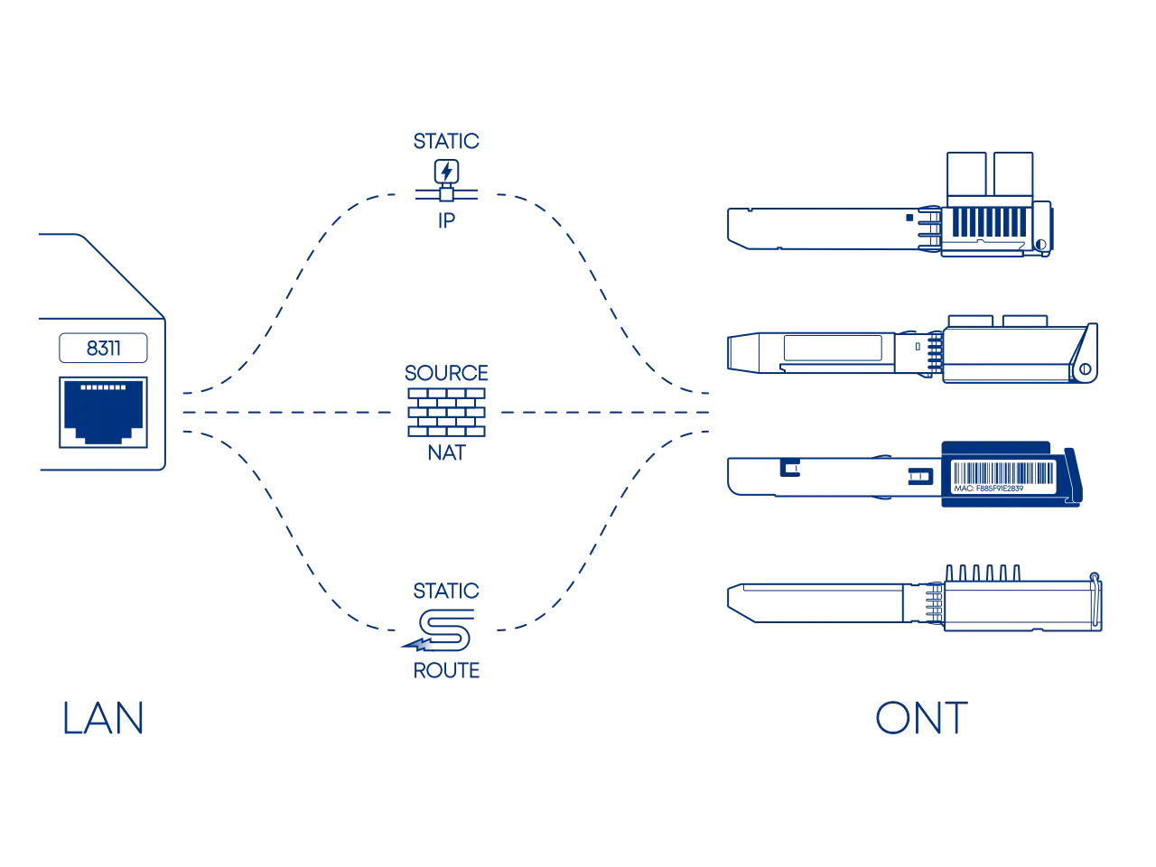
Accessing the management interface of your ONT from within your local network typically involves one of three configuration paths:
- A direct and straightforward configuration, but its practicality is usually limited to the initial setup and provisioning of the device.
- The standard for a secure and permanent configuration, seamlessly managing access from behind your router firewall.
- A workaround used only in cases where manual Source NAT (SNAT) is restricted or non-existent, such as with UniFi OS or various TP-Link offerings.
Before configuration, you must identify the ONT's management IP and subnet using manufacturer documentation, online sources, or a network scanning tool.
Default IP
Your ONT's default IP may conflict with your local network because both often use the same common Class C private range (192.168.0.0/16). To avoid this address confusion, it is recommended to move your local network to a less common private range such as Class A (10.0.0.0/8) or Class B (172.16.0.0/12). This ensures your router can clearly distinguish between your home devices and the ONT management interface.
The following ONTs commonly used in our guides have the following default IPs you will want to avoid:
| ONT | DEFAULT IP |
|---|---|
| WAS-110 | 192.168.11.1 |
| X-ONU-SFPP | 192.168.1.1 |
| HLX-SFPX | 192.168.33.1 |
| XS-010X-Q | 192.168.100.1 |
| SPS-34-24T-HP-TDFO | 192.168.1.10 |
| WT-ONU-STICK | 192.168.1.1 |
The default IP for the WAS-110 and X-ONU-SFPP can be either 192.168.11.1 or 192.168.1.1, depending on the vendor.
If the IP is unknown, the industry-standard, cross-platform tool nmap can aid in network discovery. The following examples scan the three (3) private IP address ranges (RFC 1918).
nmap -sn 192.168.0.0/16 # (1)!
nmap -sn 10.0.0.0/8
nmap -sn 172.16.0.0/12
192.168.0.0/16is the most common default range used by consumer network equipment.
Static IP Point-to-Point
A static IP on the same subnet provides direct, local access to the ONT. This approach streamlines setup by establishing a simple local connection, allowing devices to communicate directly without requiring traffic to cross network boundaries or utilize a gateway.
While this configuration serves as a foundational exercise in core networking, it represents an incomplete solution for a typical SOHO setup. In these environments, the WAN interface must simultaneously maintain a public internet connection, which is generally incompatible with a dedicated static IP.
graph TD
  classDef lanNode fill:#fff,stroke:#475569,stroke-width:2px
  classDef linkNode fill:#f1f5f9,stroke:#475569,stroke-width:2px,stroke-dasharray: 5 5
  classDef titleNode fill:#1e293b,stroke:#1e293b,font-weight:bold,font-size:14px
  classDef ontNode fill:#f8fafc,stroke:#475569,stroke-width:2px

  subgraph PC_Group ["Admin PC"]
    PC_Title("<font color=white>Host Interface: Static Config"):::titleNode
    PC("<b>NIC</b><br/>IP: 192.168.11.2<br/>Subnet: 255.255.255.0"):::lanNode
  end

  subgraph Link_Group ["Physical Layer"]
    L_Title("<font color=white>L2 Broadcast Domain / Direct Ethernet"):::titleNode
    L2("<b>Layer 2 Path</b><br/>MAC Resolution (ARP)"):::linkNode
  end

  subgraph ONT_Group ["ONT"]
    O_Title("<font color=white>Local Subnet: 192.168.11.0/24"):::titleNode
    ONT("<b>LCT</b><br/>IP: 192.168.11.1 (Static)"):::ontNode
  end

  PC_Title --- L_Title
  L_Title --- O_Title
  O_Title ---|Within ONT Subnet| PC_Title

  PC ==>|<b>IP Packet</b><br/>DST: 192.168.11.1| L2
  L2 ==>|<b>Ethernet Frame</b><br/>SRC MAC: PC<br/>DST MAC: ONT| ONT

  linkStyle 0,1 stroke-width:0px;
  linkStyle 2 stroke:#475569,stroke-width:2px,stroke-dasharray: 3 3;

  style PC_Group fill:#f1f5f9,stroke:#cbd5e1,stroke-width:1px
  style Link_Group fill:#e2e8f0,stroke:#1e293b,stroke-width:3px
style ONT_Group fill:#f1f5f9,stroke:#cbd5e1,stroke-width:1pxFor the shameless mouse clickers...
If you are more comfortable with the Windows GUI, follow the manual steps outlined by Microsoft at:
Run Command Prompt as Administrator
- Press Win+R
- In the Run dialog box, type
cmdinto the input field and then press Ctrl+Shift+Enter.
-
Identify the host Interface Name the WAS-110 is connected to.
netsh interface ip show config -
Assign a
192.168.11.2static IP address to the host interface, replacing<interface name>in the following commands with the value retrieved from step 1.netsh interface ipv4 set address name="<interface name>" static 192.168.11.2 255.255.255.0 192.168.11.1 netsh interface ipv4 set interface "<interface name>" mtu=1500Execute the following command to restore DHCP, only if the static IP was temporary for setup.
netsh interface ipv4 set address name="<interface name>" dhcp
For the shameless mouse clickers...
If you are more comfortable with the macOS GUI, follow the manual steps outlined by Apple at:
-
Launch Terminal App.
-
Identify the Network Service the WAS-110 is connected to.
sudo networksetup -listallnetworkservices -
Assign a
192.168.11.2static IP address to the host network, replacing<service>in the following commands with the value retrieved from step 2.sudo networksetup -setmanual <service> 192.168.11.2 255.255.255.0 192.168.11.1Execute the following command to restore DHCP, only if the static IP was temporary for setup.
sudo networksetup -setdhcp <service>
For the shameless mouse clickers...
Use a NetworkManager front-end. Check your distribution documentation.
The following commands set the IP address but will not persist after a power cycle
For persistence check your distribution documentation, such as Debian Network Configuration.
The following commands must be run as root su - or prepended with sudo
ip link show
ethtool <interface>
ip address show
ip address flush dev <interface>
ip route flush dev <interface>
ip address add 192.168.11.2/24 dev <interface>
ip address show dev <interface>
ifconfig <interface> 192.168.11.2 netmask 255.255.255.0
The prior command to set the IP address will not persist after a power cycle
For persistence you must edit /etc/rc.conf with the following:
ifconfig_<interface>="inet 192.168.11.2 netmask 255.255.255.0"
Source NAT Router or Firewall
Source NAT (SNAT) provides stateful translation for traffic behind the firewall to reach the ONT, which resides upstream of the firewall on the public-facing WAN interface. This translation makes the ONT's management interface appear as a reachable local network device.
This configuration typically requires that the traffic be translated to a source IP on the same subnet as the ONT LCT because the LCT is generally restricted to its own subnet. This is commonly achieved by adding a secondary IP alias to the firewall's WAN interface. This translation ensures traffic originates from this local address, which enables access and overrides default firewall rules that would otherwise block traffic to private or bogon networks on the WAN interface.
graph TD
  classDef lanNode fill:#fff,stroke:#475569,stroke-width:2px
  classDef interfaceNode fill:#fff,stroke:#64748b,stroke-width:2px
  classDef natNode fill:#f1f5f9,stroke:#475569,stroke-width:2px,stroke-dasharray: 10 5
  classDef titleNode fill:#1e293b,stroke:#1e293b,font-weight:bold,font-size:14px
  classDef ontNode fill:#f8fafc,stroke:#475569,stroke-width:2px

  subgraph LAN_Group ["Admin PC"]
    PC_Title("<font color=white>LAN Client"):::titleNode
    PC("IP: 172.17.0.100<br/>(DHCP)"):::lanNode
  end

  subgraph GW_Group ["Gateway"]
    L_Range("<font color=white>LAN Range: 172.17.0.0/16"):::titleNode
    G_Title("<font color=white>Firewall - Stateful Translation"):::titleNode
    W_Alias("<font color=white>WAN Alias/Secondary IP"):::titleNode


    L_IF("<b>LAN Interface</b><br/>172.17.0.1 (Static)"):::interfaceNode
    NAT("<b>Source NAT Action</b><br/>Replace: 172.17.0.100<br/>With: 192.168.11.2 (Alias)"):::natNode
    W_IF("<b>WAN Interface</b><br/>Public IP: 203.0.113.42 (DHCP)<br/>Alias IP: 192.168.11.2 (Static)"):::interfaceNode

    L_Range --- G_Title
    G_Title --- W_Alias
    L_IF --> NAT
    NAT --> W_IF
  end

  subgraph ONT_Group ["ONT"]
    O_Range("<font color=white>Local Subnet: 192.168.11.0/24"):::titleNode
    ONT("<b>LCT</b><br/>IP: 192.168.11.1 (Static)"):::ontNode
  end

  PC_Title === GW_Group

  PC ==>|SRC: 172.17.0.100<br/>DST: 192.168.11.1| L_IF
  W_IF ==>|SRC: 192.168.11.2<br/>DST: 192.168.11.1| ONT
  W_Alias ---|Within ONT Subnet| O_Range

  linkStyle 0,1 stroke-width:0px;

  style LAN_Group fill:#f1f5f9,stroke:#cbd5e1,stroke-width:1px
  style GW_Group fill:#e2e8f0,stroke:#1e293b,stroke-width:3px
  style ONT_Group fill:#f1f5f9,stroke:#cbd5e1,stroke-width:1px


-
Add a virtual IP to the WAN interface by navigating to Interfaces > Virtual IPs > Settings, clicking , applying the settings below, clicking Save, and clicking Apply.
Mode IP Alias Interface WAN Network / Address 192.168.11.2/24 Deny service binding VHID Group Description WAS-110 Management -
Add a firewall alias for the ONT by navigating to Firewall > Aliases, clicking , applying the settings below, clicking Save, and clicking Apply.
Enabled Name was_110 Type Host(s) Categories Content 192.168.11.1 Statistics Description WAS-110 -
Switch to Hybrid outbound NAT by navigating to Firewall > NAT > Outbound, selecting Hybrid outbound NAT rule generation, clicking Save, and clicking Apply changes.
-
Add a manual outbound NAT rule, click in the Manual rules table, apply the settings below, click Save, and click Apply changes.
Interface WAN Source address LAN net Destination address was_110 Translation / target 192.168.11.2 (WAS-110 Management)


-
Add a virtual IP to the WAN interface by navigating to Firewall > Virtual IPs, clicking Add, applying the settings below, clicking Save, and clicking Apply Changes.
Type IP Alias Interface WAN Address(es) 192.168.11.2/24 Description WAS-110 Management -
Add a firewall alias by navigating to Firewall > Aliases > IP, clicking Add, applying the settings below, clicking Save, and clicking Apply Changes.
Properties Name was_110 Description WAS-110 Type Host(s) Host(s) IP or FQDN 192.168.11.1 -
Switch to Hybrid outbound NAT by navigating to Firewall > NAT > Outbound, selecting Hybrid Outbound NAT rule generation, clicking Save, and clicking Apply Changes.
-
Add a manual outbound NAT rule, click Add in the Mappings table, apply the settings below, click Save, and click Apply Changes.
Edit Advanced Outbound NAT Entry Interface WAN Source LAN subnets Destination Network or Alias - was_110 / 32 Translation Address 192.168.11.2 (WAS-110 Management)
Follow the Accessing a CPE/Modem from Inside the Firewall guide from the pfSense documentation:
https://docs.netgate.com/pfsense/en/latest/recipes/modem-access.html
UniFi OS employs a logical abstraction layer that binds network policies to virtual interfaces (e.g., WAN, LAN) rather than physical interfaces (e.g., eth9). Unfortunately, this limits the functionality of the advanced NAT interface https://help.ui.com/hc/en-us/articles/16437942532759-DNAT-SNAT-and-Masquerading-in-UniFi. As a workaround, you must configure these settings via the CLI.
-
Enable SSH by navigating to OS Settings > Console Settings > Advanced.
https://help.ui.com/hc/en-us/articles/204909374-UniFi-Connect-with-Debug-Tools-SSH
-
Login to the UDM remote shell over SSH using a terminal client.
ssh root@192.168.1.1 # (1)!- Replace the
192.168.1.1IP with the one assigned to the UDM.
- Replace the
The following steps will not persist with the next power cycle or web UI change and must be repeated each time
-
Assign a static IP on the Ethernet interface within the same subnet as the ONT.
Interface numbers are zero (0) indexed, e.g.
eth9for Port 10ip addr add dev eth9 local 192.168.11.2/24 # (1)!- Replace
eth9with the Ethernet interface connected to the ONT.
- Replace
-
Apply a source NAT rule for the Ethernet interface and assigned IP(s).
iptables -t nat -A POSTROUTING -o eth9 -d 192.168.11.1 -j SNAT --to 192.168.11.2 # (1)!- Replace
eth9
- Replace
-
Assign a static IP on the Ethernet interface within the same subnet as the ONT by navigating to IP > Addresses. Be sure to set the interface to the correct SFP+ interface of your ONT.
Address 192.168.11.2/24 Interface sfp-sfpplus1 
-
From Apply a source NAT rule for the Ethernet interface and assigned IP(s) by navigating to IP > Firewall > NAT. Be sure to set the out interface to the correct SFP+ interface of your ONT.
Chain srcnat Dst. Address 192.168.11.1 Out. Interface sfp-sfpplus1 Action src-nat To Addresses 192.168.11.2 

Be sure to change sfp-sfpplus1 for the correct SFP+ interface of your ONT. These terminal commands will persist.
/ip/address add address=192.168.11.2/24 interface=sfp-sfpplus1 network=192.168.11.0
/ip firewall nat add action=src-nat chain=srcnat dst-address=192.168.11.1 out-interface=sfp-sfpplus1 to-addresses=192.168.11.2
Static Route Restricted environments
Static routes serve as a manual redirection mechanism in environments where granular outbound NAT controls or NAT policies are restricted or non-existent.
Configuring this route is difficult because it creates an asymmetric return path. While the router knows how to send traffic to the ONT, the ONT is typically a read-only device and does not know how to route return traffic back to the internal LAN. The 8311 community firmware overcomes this with a built-in reverse ARP daemon. This tool ensures the return path is defined and allows traffic to successfully cross network boundaries without manual ONT configuration.
graph TD
  classDef linkNode fill:#f8fafc,stroke:#475569,stroke-width:2px
  classDef titleNode fill:#1e293b,stroke:#1e293b,font-weight:bold,font-size:14px
  classDef routeNode fill:#fff,stroke:#475569,stroke-width:2px
  classDef logicNode fill:#f8fafc,stroke:#475569,stroke-width:1px

  subgraph LAN_Group ["Admin PC"]
    PC_Title("<font color=white>LAN Client"):::titleNode
    PC("IP: 172.17.0.100"):::linkNode
  end

  subgraph GW_Group ["Gateway / Router"]
    GW_Title("<font color=white>Static Route: 192.168.11.0/24"):::titleNode
    GW("WAN MAC: 00:00:5E:00:53:01<br/>WAN IP: 203.0.113.42"):::routeNode
  end

  subgraph ONT_Group ["ONT (8311 Firmware)"]
    O_Title("<font color=white>Local Subnet: 192.168.11.0/24"):::titleNode
    ONT("<b>LCT Port</b><br/>192.168.11.1"):::linkNode

    subgraph Daemon ["Reverse ARP Daemon"]
      TCPDUMP["tcpdump -i eth0_0_1_lct...<br/>Sniff ARP/IP Packets"]:::logicNode
      IP_NEIGH["ip neigh replace"]:::logicNode
    end

    ONT -.->|"3<br/>Detect Inbound Traffic"| TCPDUMP
    TCPDUMP -.-> |Extracts MAC/IP| IP_NEIGH
    IP_NEIGH -.->|"4<br/>Inject Neighbour"| ONT
  end

  PC_Title === GW_Group
  GW_Title --- |Matching Subnet| O_Title

  PC ==> |"1<br/>Target: 192.168.11.1"| GW
  GW ==> |"2<br/>Routed via WAN"| ONT

  ONT ==> |"5<br/>Frame to Router MAC"| GW
  GW ==> |"6<br/>Successful Return"| PC

  style LAN_Group fill:#f1f5f9,stroke:#cbd5e1,stroke-width:1px
  style GW_Group fill:#e2e8f0,stroke:#1e293b,stroke-width:3px
  style ONT_Group fill:#f1f5f9,stroke:#cbd5e1,stroke-width:1px
style Daemon fill:#fff,stroke:#475569,stroke-dasharray: 5 5,stroke-width:1pxThese steps are intended ONLY for DHCP or Static IP WAN connections
If your WAN is configured for PPPoE, you cannot use the GUI to create a static route to the physical WAN interface.
- Set the SFP port as the WAN interface by navigating to Network > Settings > Internet.
-
Create a static route by navigating to Network > Settings > Policy Engine > New, clicking Create New Route, applying the settings below, and clicking Add.
Route Static Name WAS-110 Device Gateway Forward Interface Interface WAN Destination 192.168.11.0/24
- Set the SFP port as the WAN interface by navigating to Network > Settings > Internet.
-
Create a static route pointing at the WAN interface. This is under Settings > Policy Table > Create New Policy > Route
Name WAS-110 Device Gateway Distance - Type Interface Value WAN Destination 192.168.11.0/24
- Set the SFP port as the WAN interface by navigating to Network > Settings > Internet.
-
Create a static route pointing at the WAN interface. This is under Network > Settings > Policy Engine > Policy-Based Routes > Create Route
Name WAS-110 Device Gateway Distance - Type Interface Value WAN Destination 192.168.11.0/24


- Set the SFP port as the WAN interface by navigating to Network > Settings > Internet.
-
Create a static route pointing at the WAN interface. This is under Network > Settings > Routing > Static Routes
Name WAS-110 Device Gateway Distance - Type Interface Value WAN Destination 192.168.11.0/24
If these steps do not match your current UniFi Network version, please refer to the official Ubiquiti guide: https://help.ui.com/hc/en-us/articles/12566175125783-UniFi-Gateway-Policy-Based-Routing
These instructions are based on TP-Link Deco app version 3.10.25. Steps may vary slightly in earlier or future versions.


- Install and set up the TP-Link Deco app using the official guide: Getting to know your Deco app.
- From the Home tab, tap More in the bottom navigation bar.
- In the More menu, tap Advanced.
- Tap Static Routing.
-
Tap the (plus) icon to create a new static route.
Name WAS-110 Network Destination 192.168.11.0 Subnet Mask 255.255.255.0 Default Gateway 0.0.0.0 Interface WAN